Socketing/Chipping
OBD0
MODS:
Auto to Manual
Parts:
Chip 27SF256 or 27SF512 work well.
28 pin dip socket.
Chippable ECU:
PR3
PW0
PM7 (To be validated)
Method:
Warm up your soldering iron.
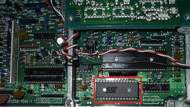
Once warmed up take the de-soldering braid or solder sucker and remove the solder from the back of the stock chips pins so you can remove it. (A quicker and easier way is to just chop the legs then de-soldering them one at a time also your less likely to damage traces this way.)
Once the stock chip has been removed make sure the holes are nice and open a bit of flux will help with soldering the socket in.
Now insert the 28 pin socket and solder the pins into place.
Insert your new chip into the socket making sure the notch (half moon) is the correct direction.

Area to work with (mine is already chipped so cant show you what it looks like with stock chip and what it looks like once stock chip is removed)

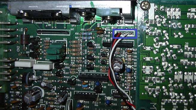
Data logging port:
Pin-out left to right.
1: Earth
2: RX (receives data from computer)
3: 5V
4: TX (sends data to computer)
5: Nothing
Only Earth,RX and TX are required to data log.
Data-logging requires a serial TTL converter.