JDM
Socketing/Chipping: JDM
MODS:
EGR-L Input
A17 PWM Output
Auto To Manual
Parts Needed:
28pin dip socket
74hc373 SMD latch 5.2mm SOP-20
5 pin header
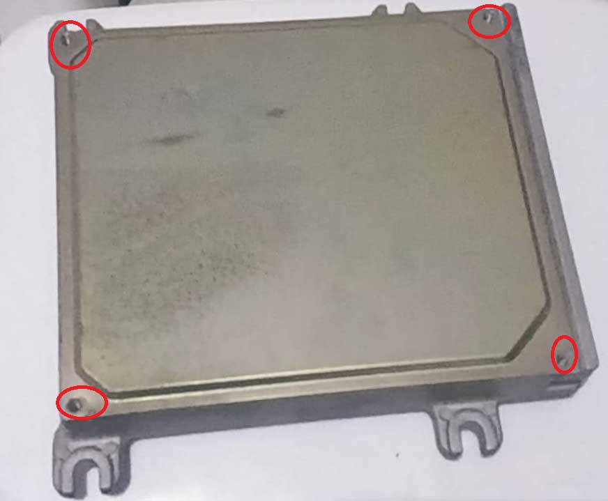
Start by removing both lids from the ECU.
All screws are Philips head.
There is one either side in each corner.
Now find the section that looks as imaged below.
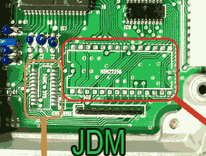
The larger 28pin socket you want to suck all the holes out using a solder sucker.
Using a flux pen and desoldering wick also helps do a tidy job.
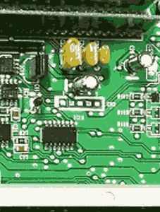
Now do the Same on the datalogging header.
The next part to install is the 74hc373 SMD latch.
In my image everything has already been soldered in.
There are two methods for soldering this part.
Use a hot air soldering station.
Or use a normal low wattage soldering iron with a small tip.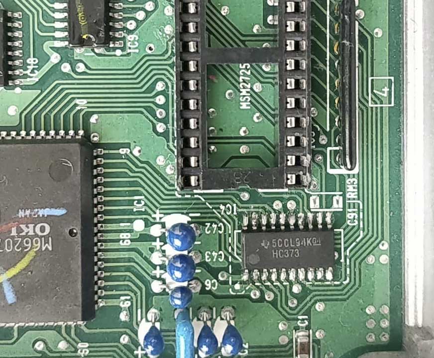
A tip for when using a soldering iron is you can put a little bit of blue tac or double sided tape under
the IC to hold it in place,
It is now good pratice to check the connections.
Test pinout:
ECU - Latch
1-----20
3-----15
4-----12
5-----16
6-----19
7------9
8------6
9------5
10-----2
11-----3
12-----4
13-----7
14-----1 & 10
15-----8
16-----18
17-----17
18-----13
19-----14
(Pin 11 on the latch goes to pin 22 on the MCU)
If thats good.
Solder in the socket and datalogging pin header.
Now by the datalogging pin header find J4 which is a resistor with 000 on it.
Remove carefully remove this resistor.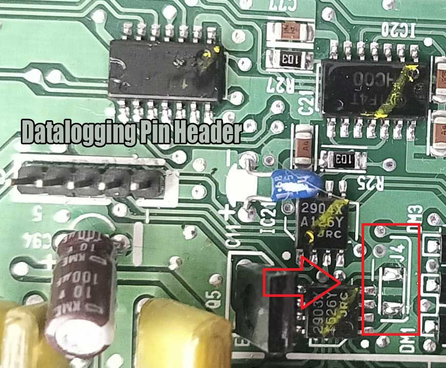
Turn the ECU over and find J1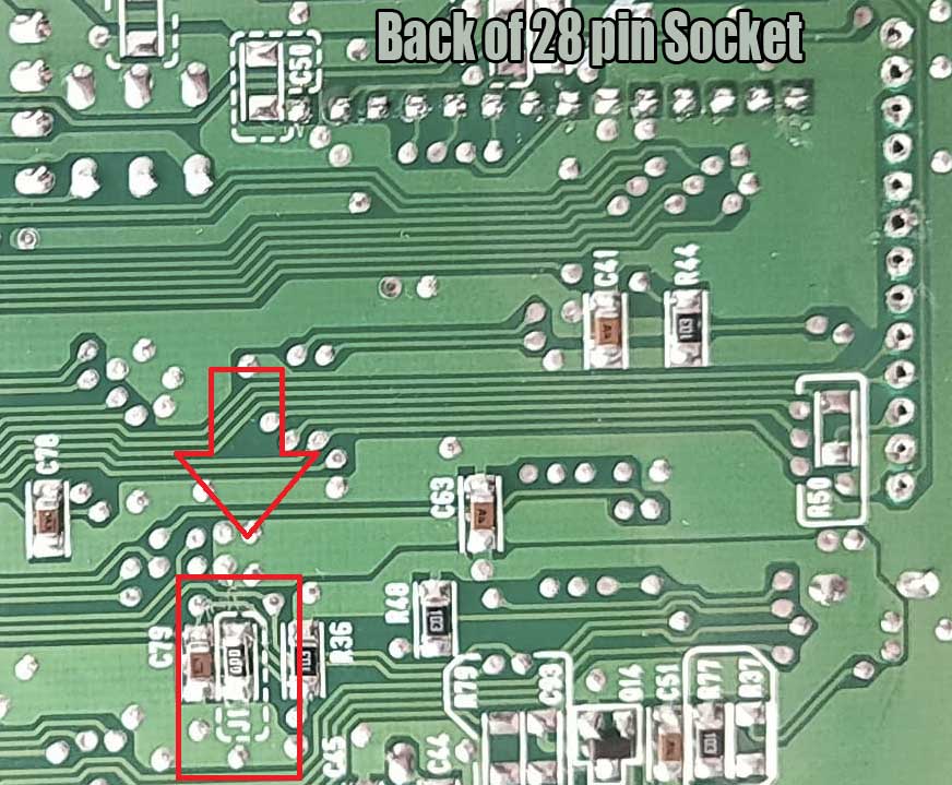
Solder the resistor you removed from J4 into J1. It can go any direction.
This will enable the socket to be read by the ECU.
Unconnecting J1 again will disable the socket so ECU runs as factory again if your having issues with a chip.